| LAPD Protocol (N-ISDN) | Home |

Certifications

Cisco

Downloads

IP
PC

Protocols

RemoteAccess

Security

Telecommunications

Tools

Unix

Web
LAPD Protocol : N-ISDN
1. Introduction
ISDN stands for "Integrated Services Digital Networks", and it's a ITU-T (formerly CCITT) term for a relatively new telecommunications service package. ISDN is basically the telephone network turned all-digital end to end, using existing switches and wiring (for the most part) upgraded so that the basic "call" is a 64 kbps end-to-end channel. It offered by local telephone companies, but most readily in Australia, Western Europe, Japan, and portions of the USA. In France, ISDN is known as "RNIS".From the point of view of the network, there are three key benefits from the ISDN technology. First, a network configuration based entirely on digital transmission and switching offers the reduced cost, lower power consumption, and easier maintainability that are general characteristics of digital equipment. Second, the higher level of function types, services and user applications on a single network are expected to result in a higher utilization of the network resources, with corresponding increase in revenues. Service integration offers the possibility of integrated network management, maintenance, and billing, leading to important reductions in cost and complexity. A third major benefit to the network lies in its ability to provide a variety of data communications services over a single digital subscriber line.
2. Physical Interfaces
An understanding of the format of interfaces and channel type is critical to any analysis of ISDN because they provide the framework through which the protocols and applications flow. ISDN defines a full network architecture as shown Fig. 1. This architecture separates access functions from actual network functions.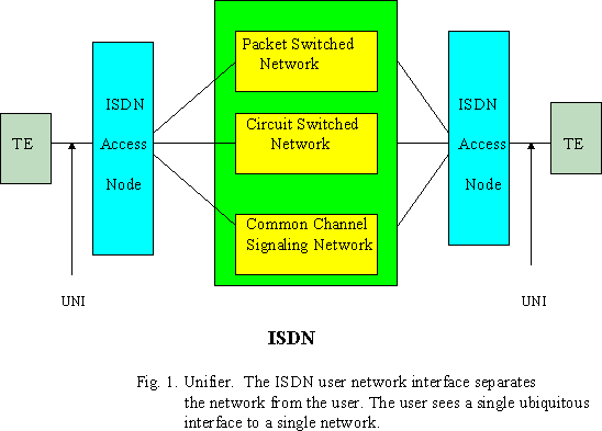
Network termination(NT) equipment handles the communications from the network while the terminal equipment(TE) is responsible for the communications from the user. NT1 includes functions equivalent to the OSI's Physical layer. These functions include line termination, Layer 1 line maintenance and performance monitoring, timing, and Layer multiplexing.
In contrast, NT2 devices are usually more intelligent than NT1 devices. NT2 devices perform the link layer functions and usually network functions as well. an NT2 devices may be a switch, multiplexer, LAN, PBX, or a terminal controller. NT12 is a single device that has the functionality of an NT1 and NT2. NT12 will handle the physical, link, and network layer protocols.
TE includes functions equivalent to Layer 1 and higher. Examples of TE are digital telephones, data terminal equipment, and integrated workstations. TE functions include protocol handling, maintenance, and interfacing. TE1's interface compiles with the ISDN user-network interface(UNI); TE2's does not. TA includes functions equivalent to Layer 1 and higher. It enables a TE2 to be served by an ISDN user network interface.
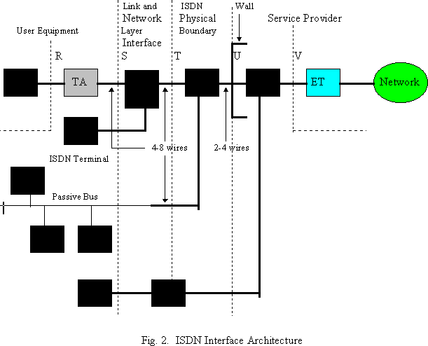
The S/T interface is intended for use on the two twisted-wire pairs(four-wire twisted pairs)-one to transmit and one to receive- ,allowing full-duplex communication, between the subscriber terminal equipment and the remote PBX terminal. U interface is a full-duplex running over a single pair of twisted wires between the subscriber terminal equipment and the central office switch, or between a network termination 1(ISDN destination NT1) and the central office switch. The conversion from four to two wires (NT1 to LT), needed to maintain consistency with current telephone networks, is done by an echo-canceling algorithm.
The range of S and T interface is 3300 feet (1000 m) in a point-to point configuration or up to 500 feet(150 m) in a multidrop passive-bus configuration. The U interface will have a maximum length of 2500 to 6500 m. The T bus is a multipoint bus. It is sometimes called passive bus because there are no repeaters on the line between the NT1 and the devices(TE1). It can be implemented using the same cable and connectors as is 10 base T Ethernet. There may be up to 8 devices on the S/T bus. The bus may be formed with splitters and T connectors- it is bus, not a star. The D channel is used to control the attachment of the one to eight devices to the two B channels. No two devices attach to the same B channel at the same time.
3. Channel Types : BRI and PRI
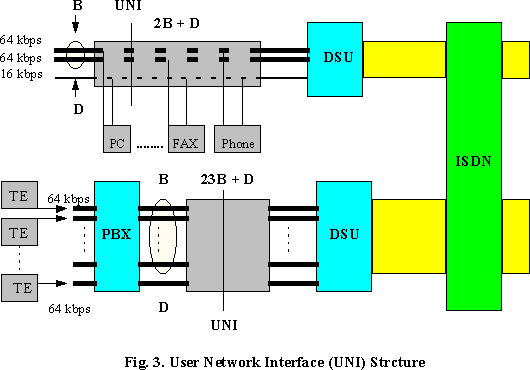
There are two types of ISDN services, Basic Rate Interface(BRI), operating at 192 kbps, and Primary Rate Interface(PRI), operating at 1.544 Mbps in North America or 2.048 Mbps in Europe. Both services support two common kinds of channel types, the "B" (Bearer) and the "D" (Data).- BRI consist of two B channels at 64 kbps and one 16 kbps D channel, which is called 2B+D. The BRI has 144 kbps information carrying capacity.
- PRI is designed to accommodate applications requiring more than two simultaneous connection and/or data rate in excess of 64 kbps. The two distinct configurations are 23B+D structure at 1.544 Mbps and 30B+D running at 1.920 Mbps. In some cases more than one PRI connects between equipment.
4. Data Link Layer Protocol : LAPD
4.1 Basic function of LAPD protocolISDN standards are constructed using the Open System Interconnection seven-layer reference model. Layer 2 (data link) protocol for the D channel(called Link Access Procedure-D) is used to convey messages over common D channel. The LAPD and higher layer protocols handle the handshaking(commands and responses), signaling, and control for all of the voice and data calls that are setup through the ISDN D channel. The LAPD protocol evolved from LAPB of the CCITT x.25 protocol in order to serve multiple terminals on a single subscriber loop. LAPD allows multiplexing of layer 2 connections on the same physical connection. Eight users can have simultaneous D channel sessions. Each user is assigned a Logical Channel Number(LCN) and bandwidth is divided accordingly. The objective of LAPD is to provide a secure, error-free connection between two end-points so as to reliably transport Layer 3 messages. LAPD protocol provides framing, sequence control, error detection, and recovery of multiple logical data links on the same D channel. The Layer 2 operation starts with a Layer 3 request to establish a call, which prompts Layer 2 to demand Layer 1 to initiate the start-up procedure. Afterwards Layer 2 initializes itself through the SABME ( Set Asynchronous Balanced Mode Extended) procedure. The SABME is conducted between two peer processes by means of unnumbered frames. Initialization guarantees that the correct sequence numbers are used in processes on both ends. Layer 2 protocol maintain the correct sequence of information due to many different types of error. Firstly, if frames lost more than three consecutive times, the re-establishment of the LAP will be done under the assumption that the connection has failed. Secondly, a timer mechanism and preset values of time-out intervals detect lost frames in the transmit direction. Thirdly, frames received out of sequence denote a lost frame in the receive direction. Finally, frame Check Sequence(FCS) value control and discard frames corrupted by errors due to noise.
The LAPD protocol involves two major functions :
- The bit-level protocol that deals with such operations as framing and cyclic redundancy error checking ( CRC); and
- The element of procedure that deals with the handshaking between peer entities at both source and destination terminal equipment.
4.2 Layer 2 Frame Structure
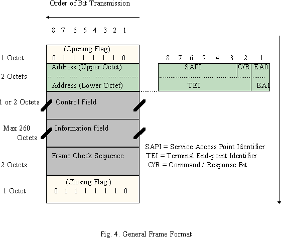
LAPD protocol operations are based on the exchange of Layer 2 frames which consists of several components as shown in Fig.4. The frames contain an integral number of octets that are transmitted in increasing order from top to bottom. Every frame contains at most six fields, opening flag, address, control, information, frame check sequence, and closing flag. Certain frames do not contain information field. The flags consist of one octet each and address and frame check sequence field consist of two octets each. The size of the control field may be one r two octets, depending on the specific type of frame. The information field carries higher layer data and the size of the information field is variable in length with a system dependent. However, the size is restricted to a 260 octets maximum.
- Flag Field
The opening and closing flags are used for frame synchronization. The flags of a frame serve as a unique marker to delimit its beginning and end and consist of the symmetric bit pattern 0 1 1 1 1 1 1 0. The closing flag may also used as the beginning flag of the next frame. This unique bit pattern should not be existed in between the opening and closing flag field. To avoid their occurrence in the remaining fields of the frame bit stuffing technique is used. The data link layer entity at the sending side examines the content of the frame between opening and closing flags during transmission and insert a 0 bit after every five consecutive 1 bit. The data link layer entity at the receiver side inverts this process by discarding any 0 bit that directly follows five 1 bits in a sequence.
- Address Field
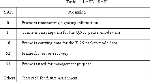
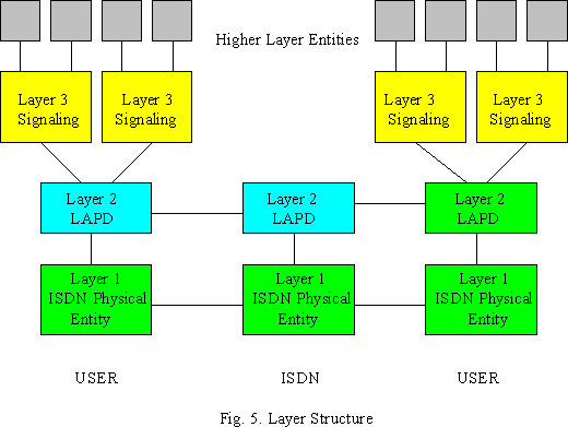
The opening flag of a frame is followed in octet 2 and 3 by an address field. In order to have each device support multiple logical data links, the data link address is divided into the Service Access Point Identifier (SAPI) and the Terminal End point Identifier (TEI). These two fields are together called Data Link Control Identifier (DLCI). This provides a form of multiplexing. The six bits allocated to the SAPI allow the specification of up to 64 distinct service access point. Table 1. is representing the meaning according to the different SAPI values. The SAPI identifies the network entity for which the information in the LAPD frame is intended. A LAPD entity may have more than a single Layer 3 entity above it and therefore will have more than one SAPI in use (Figure 5).
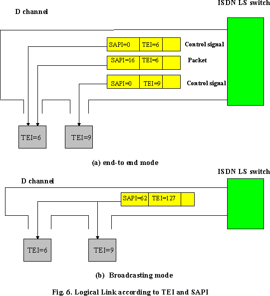
The TEI is associated with the user side of the user-to network interface. The TEI identifies the logical terminal or final destination for the Layer 3 information. One or more TEIs can be used for point to point data transfer. The TEI for broadcast connection occurs when a message is transmitted with the TEI set to 127. Broadcast TEI will be transmitted to all the logical terminals on the Layer 3 entity (Figure 6). The TEI is either assigned by the TEI management entity automatically or by the user. In either case no two TEIs can be the same. Table 2 is showing the TEI values.
The remainder of the address field consists of a single bit that identifies the frame as a Command or Response (C/R) frame. The TE will set the C/R bit to one for responses and reset it to zero for commands. The network side does the opposite, setting the bit for commands and responses. Bit 1 in octet 2 set to 0 (EA0) means that another address is to be transmitted, and bit 1 in octet 3 set to 1 (EA1) indicates that the associated address is the last one in the transmission.

- Control Field
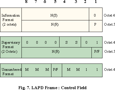
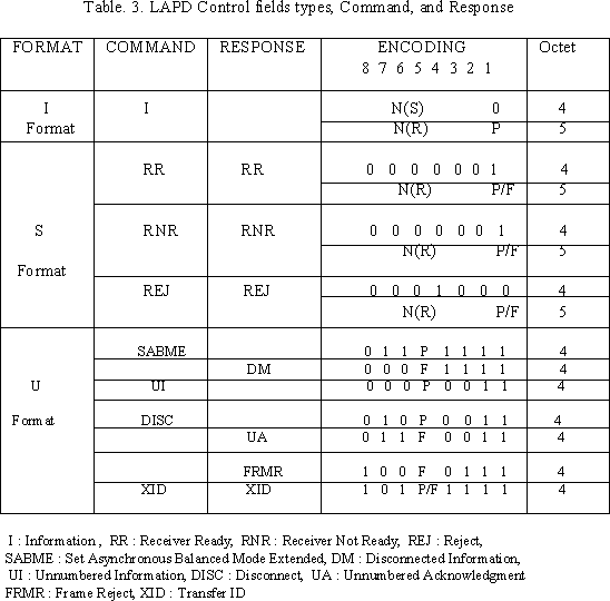
The control field determines the type of LAPD frame being transmitted as well as containing the sequence numbers for the acknowledged information transfer service. The structure of the control field is shown in Figure 7 and it occupies either octet 4 or octets 4 and 5 depending on the type of frame. There are three different formats for the control field, I-format, S-format, and U-format frame. The numbered information transfer format (I-format) frames are used to transfer information between network layer entities. I-frame frame has a send sequence number, N(S), a receive sequence number, N(R), and a poll bit. The supervisory format (S-format) frame has N(R) field in the control field but not N(S) field. The N(S) and N(R) counters occupy seven bits in the control field. It gives the range 0 to 127. The single bit identified as P or F in the control field format is refereed to as the poll bit in command frames and the final bit in response frames. P is set to 1 by a data link layer entity to elicit or poll a response frame from its peer entity on the other side of the connection. F must be set to 1 in the response frame resulting from the poll command frame. In the I- format frames, there is not F bit, so I-format frame never used as a response to command. The unnumbered format (U-format) frame provides additional functionality and is used for information transfer during unacknowledged information transfer. Modifier bits (M) in the U-format frame are used to define seven different frames. The purpose of U-format frames are establishing, maintaining, and disconnecting a data link connection between peer data link layer entities. Table 3 is listing the command, response, and different LAPD control field types.
- Frame Check Sequence (FCS) Field
The frame check sequence(FCS) provides the detection by the receiver of any errors that may have occurred during the transmission of a frame. The FCS is the standard 2-byte CCITT-16 cyclic redundancy checksum. The computational procedure is derived from the theory of cyclic codes.
5. Comparison of the Software and Hardware implementation of LAPD protocol
Doing the LAPD in software is more costly and less efficient than the hardware based alternative. The software implementation requires a DLC to handle address field recognition, and a microprocessor. The DLC takes care of the bit-level protocol. LAPD's element of procedure is done in software which size is about 12 to 16 kbyte program. When DLC receives data, it performs the address field recognition, check the CRC bits, remove the header, then if the address of the data is matched, interrupts the microprocessor on a character by character. The frequent interruption will reduce the processing time. Using this software intensive approach cannot handle the LAPD protocol at data rates higher than 64 kbit/s, full duplex. On the other hand, in the hardware intensive approach, the microprocessor interruption can be reduced. Two DLCs are used for the hardware implementation. The built in DMA controller and some other hardware perform address recognition. The controller reduce the excessive host overhead caused by interrupts. Eventually, the processor receives the interrupt signals only at the end of each data frame. This allows it to dedicate more processing time to the higher layer protocol.References
- Helgert, Hermann J. Integrated Services Digital Networks: Architecture, Protocols, Standards. NewYork: Addison-wesley, 1991
- Fritz, Jeffrey Neil, Sensible ISDN Data Application. West Virginia University, 1992
- Ince, A. Nejat, et al. Planning and Architectural Design of Integrated Services Digital Networks. Boston: Kluwer Academy, 1995
- Park, Pan Gyu. ISDN: transmission, switching technique. Dongseo press, 1995
- Chen, Po. Data communication: How to make the most of ISDN's new LAPD protocol., McGraw-Hill, August, 1987
- Falek, James G. Data communication: Standards makers cementing ISDN subnetwork layers. McGraw-Hill, October, 1987
- Sazegari, Steven A. Data communication: Network architects plan broadening of future ISDN. McGraw-Hill, July, 1987
- Wolf, Dean. Data communication: Making the most of ISDN now. McGraw-Hill, August, 1989
- http://alumi.caltech.edu/~dank/isdn
This page was created in 0.09076 seconds
Comments and Questions
Last modified: October 26 2003.
Last modified: October 26 2003.