| BCRAN Study Guide | Home |

Certifications

Cisco

Downloads

IP
PC

Protocols

RemoteAccess

Security

Telecommunications

Tools

Unix

Web
Building Cisco Remote Access Networks
Overview
The BCRAN test is 77 questions in length, allows for 90 minutes of testing time, and covers the following topics:
- Cisco router product groups
- Wan Connectivity - X.25, T1, E1, Frame Relay, ISDN BRI & PRI, analog dial-up
- Bandwidth requirements and bandwidth on demand
- Async connectivity pin-outs, modem configuration, troubleshooting, and configuration
- Dial-up Networking, windows configuration, modem attributes
- Cisco 700 setup, configurations, profiles
- Security - PPP, CHAP, PAP, TACACS, AAA, Kerberos V, and callback
- Multilink PPP, dialer profiles, and DDR
- Queueing and Compression
- NAT
- Troubleshooting and debugging
ISDN
Description and Interfaces
ISDN BRI = Basic Rate Interface
DS0 = Digital Signal Level 0 = 64Kbps
ISDN PRI US T1 = Primary Rate Interface -- Use of CSU/DSU requires different connectors. Uses DB15 and RJ48 connections.
DS1=1.54Mbps = 24 DS0’s; i.e., 23 64Kbps B (Bearer) channels and one 64Kbps D (Delta or Data) channel plus the 8Kbps overhead needed for framing.
ISDN PRI EUROPE E1 - 30 X DS0
In Europe, the ISDN service provider provides the NT1. In the US, the customer
supplies the NT1.Logical Interfaces
Note: NT1 and NT2 can be combined into one device.
RSTUV-Logical Reference Points
Rate Reference Point - Located between the NON ISDN router interface and the Terminal Adapter (TA).
Example of TE2: Async/Sync Serial, non-ISDN phone
System Reference Point - Is the reference point between the ISDN user terminals and the NT2 or TA and NT2. Non-US demarcation.
Example of TE1: ISDN phone, Some teleconferencing Equipment
Terminal Reference Point – This is the reference point between the NT1 and NT2 (Customer Switching Equipment/PBX). This reference point is included in the NT1 as well. This point is NON-US demarcation.
Example of NT2: PBX, multiplexer
User Reference Point - This reference point is a US demarcation. It references the point between the NT1 and the LT.
Example of NT1: ADTRAN ISU, 3Com TA
V Reference Point - Located between the LT and the ET. Also referred to as the local exchange.

ISDN Protocols - ITU-T groups the protocols, interfaces and addressing.
- E-series - describes telephone network; e.g., E.164=International addressing for ISDN.
- I-series - describes Interfaces & Concepts; e.g., I.430=BRI Interface.
- Q-series - describes switching and signaling. (e.g., Q.921=LAPD Link Access Procedure D channel, Q.931 DSS1 Digital Subscriber Signaling #1)
Configuring ISDN BRI
- Select your switch type (provided by your carrier).
Router2(config)# isdn switch-type basic-dms100
Note: Before 11.3T, the IOS would support only one switch-type that was defined globally!
Router2(config-if)# isdn switch-type basic-dms100
- Configure the appropriate interface on the router.
Router2(config)# interface bri X (x = the interface you are going to configure)
For a TE2 non-ISDN interface use the 'interface serial x' command -- but there is no need to define a switch-type or SPID in this case.
Router2(config)# interface serial X (x = the interface you are going to configure)
- Set SPID's (Service Profile Identifiers). The service provider assigns these numbers.
Router2(config-if)# isdn spid1 512790203300 [local directory number]
Router2(config-if)# isdn spid2 512790203400 [local directory number]
- Set the appropriate protocol for encapsulation and set the protocol for authentication. PPP or HDLC can be used for encapsulation. CHAP or PAP can be used for authentication. CHAP is encrypted; PAP sends information in plain text.
Router2(config-if)# encapsulation ppp
Router2(config-if)# ppp authentication chap
Dial on Demand Routing (DDR)
DDR for ISDN - Use DDR for connections that do not need to be connected for long periods of time. Determine what traffic is "interesting" and needs to bring up the link or reset the idle timeout. Use access lists to deny broadcasts such as SAP updates and permit traffic that needs to be interesting. You can also use the passive interface command to prevent the forwarding of routing updates; e.g., IGRP, OSPF, EIGRP
dialer-list [number] protocol [ip|ipx|bridge] [list|permit] is the global command used to define interesting traffic as all traffic of a certain protocol, or point to an access list that defines interesting traffic more specifically. There can be multiple dialer-lists – one per protocol, including IP, IPX, NETBIOS, BRIDGE, DECNET, etc.
Backup Interfaces Load and Outage - This is important for fault tolerance and useful when interfaces exceed the expected load. Follow these simple steps to backup an interface:
- Define what traffic is interesting. An access-list command can be referred to from this dialer-list command to specify the appropriate traffic to raise the link or stop the idle-timer countdown.
Router2(config)# dialer-list 3 protocol ip permit (all ip traffic is interesting)
Or
Router2(config)# dialer-list 3 protocol ip list 5 (use access-list 5 to define interesting traffic)
Router2(config)# access-list 5 permit 10.98.98.0 0.0.0.255 [all traffic sourced from the 10.98.98.0 network is interesting]
- Assign the dialer-list to the appropriate interface.
Router2(config-if)# interface bri 2
Router2(config-if)#dialer-group 3 (use dialer list “3” to monitor for interesting traffic)
- Assign the destination. Use the dialer map command to specify the destination parameters.
Router2(config-if)# dialer map ip 10.180.0.3 name router3 5125551092
- Determine which call options to use. To use DDR successfully, you must specify the appropriate call values.
Router2(config-if)# dialer fast-idle 30 (if the interface is busy and another call needs to be placed, the 30 parameter specifies to disconnect the call if the line is idle for over 30 seconds; the default is 20 seconds)
Router2(config-if)# dialer idle-timeout 180 (tells the interface to disconnect after idle for 180 seconds; the default is 120 seconds)
Router2(config-if)# dialer load-threshold 128 [either|outbound|inbound] (numerical value 1 through 255 represents x/255 -- tells the router at what load to make another call)
Rate adaptation - The data speed of an ISDN line can be slowed down to 56K if necessary. Use the speed option with the dialer map command.
Router2(config-if)# dialer map ip 10.180.0.3 name router3 speed 56 broadcast 5125551038 (makes a 56K call to router3 at 5125551038, will pass multicasts and broadcasts to router3)
For OUTAGE Backup
- Select the interface you want to backup.
Router2(config)# interface serial 0
- Define the interface you want to use as backup.
Router2(config-if)# backup interface bri2
- Set when you want the backup line to come up. Set on/off parameters.
Router2(config-if)# backup delay 60 30 (the 60 parameter designates ON after bri2 is down for 60 seconds) (the 30 parameter designates OFF after serial0 is back online for 30 seconds)
For LOAD Backup
Use the backup load command to back up the primary line on a load basis rather than outage basis. Values are based on percentages.
Set the bandwidth ON/OFF values for the backup interface.
Router2(config-if)# backup load 50 10 (50 designates ON when bri2 exceeds 50% of bandwidth) (10 designates OFF after the combined load reaches less than 10 percent of the primary line’s bandwidth)
Debugging
The following commands can help you to troubleshoot ISDN issues
- show interface bri
- show dialer
- show isdn status
- debug isdn q922
- debug isdn q933
Pool-Members
Each DS0 can be configured to function as a separate resource that can be used to for connectivity by a dialer profile. To configure this, do the following
interface dialer 0
  ip unnumbered loopback 0
  encapsulation ppp
  dialer remote-name Remote0
  dialer pool 1
  dialer string 5551212
  dialer-group 1
interface BRI 0
  encapsulation ppp
  ppp authentication chap
  dialer pool-member 1
interface Serial 0
  ip unnumbered loopback 0
  backup interface dialer 0
  backup delay 5 10
ISDN PRI
ISDN Protocols - ISDN uses several protocols; which protocol each channel uses is crucial to understanding how ISDN works.

PRI Functional Groups and Reference Points - Since an ISDN PRI requires the use of a CSU/DSU the logical groups and reference points are much easier to identify. Note that the above diagram is for PRI and BRI.
ISDN PRI can be configured in five easy steps. SCFLC (Swami Can Fix Left-handed Clocks) can be used to remember the steps. For PRI you configure:
- Switch type
- Controller
- Frame type
- Linecode
- Clocksource
Syntax to configure ISDN PRI:
- Select your switch type.
isdn switch-type primary-5ess
- Choose the controller.
controller T1 slot/port
controller T1 2/1
- Specify the frame type.
framing esf
- Specify the linecode.
linecode b8zs
- Specify clocksource
clock source line primary [internal | secondary]
Here are the common line coding and framing types. They will typically be seen together:
ISDN PRI can accept incoming calls voice/speech calls by using the following command: (under the interface serial x:23, where x=the controller number)
isdn incoming-voice modem
ISDN Physical Interfaces – SERIAL
- EIA/TIA 232
- EIA/TIA -449
- EIA -530
- X.21
BOD Bandwidth on Demand - Can be used on BRI or PRI channels to supply additional bandwidth once a channel is connected. The traffic trigger can be set for inbound, outbound or either. The value metric is 0-255. (255 equals 100%) Example:
Dallas2(config)# interface bri 0
Dallas2(config-if)# dialer load-threshold 128 either (specifies 50% load, either direction, and brings up additional line)
ISDN Caller ID Screening - ISDN can also be configured to only accept certain calls from certain numbers. X's can be used as wildcards. Example:
Dallas2(config-if)# isdn caller 555xxxx (allows any inbound call from 555 exchange)
X.25
X.25 is a packet switched protocol that operates at the Physical, Data Link and Network Layers of the OSI model. This protocol works by encapsulating the layer 3 protocols such as IP, IPX, decnet, PPP and Appletalk. The max speed for X.25 is 128K. X.25 was engineered for strong error checking and flow control at layers 2 and 3. X.25 uses LAPB, is very reliable, and also uses sliding windows (much like TCP/IP) for flow control. Options for flow control on the interface must match the remote router. X.25 uses SVC's (Switched Virtual Circuits) and PVC's (Permanent Virtual Circuits). PVC's are always connected. Use “show interface” to view configuration. X.25 is considered the predecessor to frame-relay.
X.25 devices include DTE, DCE and PAD and uses LAPB (Link Access Procedure Balanced) as a Data Link Layer protocol.
Datagram Encapsulation
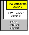
The protocol known as X.25 encompasses the first three layers of the OSI 7-layered architecture as defined by the Internation Organization for Standardization (ISO) as follows:
- Layer 1:The physical layer is concerned with electrical or signalling. It includes several standards such as V.35, RS232, and X.21.
- Layer 2:The data link layer, which is an implementation of the ISO HDLC standard called Link Access Procedure Balanced (LAPB) and provides an error free link between two connected devices.
LAPB FieldsData, Flag, FCS, Address, and Control
The flag delimits the beginning and end of a LAPB frame. It also carries the address of the DTE/DCE. Bit stuffing is used to ensure that the flag pattern does not occur within the body of the frame. The control field contains command and response information by indicating the frame function, for example receiver ready or disconnect. The Data field contains upper-layer data in the form of an encapsulated PLP packet. The FCS handles error checking and ensures the integrity of the transmitted data. Finally, the address indiciates whether a frame carries a command or a response.
- Layer 3:The network layer provides communications between devices connected to a common network. In the case of X.25, this layer is referred to as the X.25 Packet Layer Protocol (PLP> and is primarily concerned with network routing functions and the multiplexing of simultaneous logical connections over a single physical connection.
PLP Modes - Call Setup, data transfer, idle, call clearing, and restarting
PLP Packet Fields - GFI, LCI, PTI, and User Data
PAD - also known as a Packet Assembler/Disassembler, this is responsibly for assembling, buffering, and disassembling X.25 traffic between the DTE and DCE when the X.25 protocol is not understood.
Network Function - X.25 is highly available and used worldwide.
PAD - Is a Packet Assembler Dissembler between the DTE and DCE device.
It collects the data transmissions from the terminals/DTE and gathers them into a X.25 data stream and vice versa. A Cisco router can act as a PAD. During configuration of the X.25 you specify whether the interface will act as a DCE or DTE ('encapsulation x25 [dte|dce]'). When configured as a DCE the router behaves as an X.25 switch.

X.121 - Is the addressing standard. Static mappings must be made manually. X.25 does not support ARP or inverse-ARP. The addressing standard is a 3-digit country code followed by a 1-digit Service Provider code. The following 8 to 11 digits are assigned to the X.25 host.
To configure an X.25 interface for SVC - Define the encapsulation, assign the X.121 address and use map statements to link the X.121 logical address with the IP protocol or other addresses. Options for flow control must match on both sides.
Steps to configure X.25 on an interface:
SanAton2(config)# interface serial 2
SanAton2(config-if)# encapsulation x25
SanAton2(config-if)# x25 address 3167012345678 (316 country code, 7 is the service provider, the rest of the number specifies the x25 host address)
SanAton2(config-if)# ip address 10.98.98.25 255.255.255.0 (configures the IP address for the interface)
SanAton2(config-if)# x25 map ip 10.98.98.24 3160987654321 broadcast (maps the target IP address to the x121 address)
To configure an X.25 interface for PVC - Exactly the same as above except for the last step. You use the pvc command instead of the map command to establish the PVC.
SanAton2(config-if)# x25 pvc 6 ip 10.98.98.24 3160987654321 broadcast (maps the target IP address to the x121 address on virtual circuit #6)
Options for X.25 - Windows and packet sizes must match on both sides of the connection. Use the x25 ips command for incoming packet size and x25 ops for outgoing packet size. Window size uses a counter for when to send an acknowledgement. x25 win and x25 wout commands are used. The modulo controls the size of the window; 8 or 128 is used to specify the number of packets.

Frame Relay
Physical Layer - Serial interfaces use DB-60 connectors. Frame relay requires the use of a CSU/DSU. Like X.25, frame relay uses SVC's and PVC's. PVC's are used for frequent and long connection times. SVC's are for sporadic infrequent traffic. List settings with show interface command or show frame-relay map command.
Example, EIA/TIA232 EIA/TIA449 .V35 X.21
Frame Relay Bandwidth - Max throughput is 2 Mbps to 56 Kbps. Frame relay is a layer 2 protocol. It uses the upper layer for error correction. It is faster than x.25.
LMI - Line Management Interface is the standard for signaling. There are three types:
Cisco LMI is the default signaling. Service provider will specify the LMI in use.
- LMI's control data keep alives and verify the dataflow.
- Use multicast mechanism to provide network server to the DCLI.
- Use multicast addressing so DLCI has global significance.
- Verifies the DLCI's in use and the status to the local Frame relay switch.
LMI Autoconfigure - A router with IOS 11.2 and newer does not need to be configured for the LMI. The newer IOS will send all three to the FR switch until the switch responds.
DLCI - Data Link Connection Identifier verifies the logical circuits in use and the status from the CPE to the Frame Relay switch.

DLCIs have local significance only.
DLCI states are:
- Deleted - No LMI signal is being received from switch or no service is available from switch.
- Active - Lines are up; connections are active. Routers are exchanging data.
- Inactive - Frame relay switch to local connection is working. The remote routers’ connection to the frame switch is not working.
- Encapsulation Types – Choices are Cisco and IETF. Cisco is the default. If the router is a non-Cisco router, use IETF. This designation can be made per DLCI. Even if all the routers are Cisco, you can communicate with a location with a non-Cisco router. Specify the IETF encapsulation and DLCI. You can use this with the map command. In short, encapsulation can be set per interface or per destination.
Example:
Dallas2(config-if)# frame-relay map ip 10.98.98.24 25 broadcast IETF (25 = the DLCI#)
Steps to configure frame relay:
Select the interface.
Dallas2(config)# interface serial 3
Is the interface a DTE or DCE?
Dallas2(config-if)#frame-relay intf-type ?
dce Configure a FR DCE
dte Configure a FR DTE
nni Configure a FR NNI
3Assign an IP address to the interface.
Dallas2(config-if)# ip address 10.98.98.25 255.255.255.0
Select the encapsulation mode.
Dallas2(config-if)# encapsulation frame-relay cisco (this is an example of setting the encapsulation per interface. All traffic leaving interface will be Cisco.)
Set the LMI (not necessary with IOS 11.2 and up).
Dallas2(config-if)# frame-relay lmi-type [cisco|ansi|q933a]
Map protocol.
Dallas2(config-if)# frame-relay map ip 10.98.98.24 25 broadcast [cisco|ietf]
Troubleshooting
Dallas2#show frame-relay ?
Dallas#show interfaces serial ?
<0-1> Serial interface number
2501#debug frame-relay ?
Split Horizon and Routing Updates - Since routing updates should not be sent out the same interface you learned the update from (this causes routing loops), the solution to fixing this problem is creating subinterfaces with different DLCI's. Example:
Each subinterface has its own DLCI enabled multipoint connection. Routing updates will now work properly.
Traffic Shaping - Since the speed of the frame relay circuits can vary, it is important to control how much and which traffic is sent or received on an interface.
Queuing - Priority, weighted, fair and custom queuing allow for specialized control of the traffic.
Rate Enforcement - You can configure the maximum amount of traffic to pass out the interface by setting the transmission rate. Usually determined by the CIR (Committed Information Rate)
BECN/FECN Support - Dynamic monitoring of the congestion of the frame relay network. Requires Cisco IOS 11.2 or higher to support BECN monitoring.
FECN – (Forward Explicit Congestion Notification) When the frame relay switch becomes congested, it sends a FECN to the destination.
BECN – (Backward Explicit Congestion Notification) When the frame relay switch becomes congested, it sends a BECN to the source.
To use traffic shaping with the BECN support, use the following commands: *Note uses map classes.
Dallas2(config)# map-class frame-relay foo
Dallas2(config-map-class)# frame-relay adaptive-shaping BECN
Enable rate adjustment in response to BECN (enabled by default)
Dallas2(config-map-class)# frame-relay traffic-rate 56000 128000 (56000 specifies the average, 128000 specifies the peak rate)
Dallas2(config-if)# frame-relay traffic-shaping
Dallas2(config-if)# frame-relay class foo
Modems and Async
There is no clock (hence the term) and must maintain in-band timing.
Physical Interfaces – (RJ11 or DB25) The connection from the router is a DB60 connection.
Use DTE lock to avoid speed mismatch. Modem often tries to match the inbound transfer rate of the modem to the DTE. Set speed under TTY line and at modem with AT commands.
Interface Async/TTY Line Configuration Commands:
Below is the configuration necessary to configure a modem on an asynchronous interface such as AUX port or internal modem. This will allow EXEC prompt access to the router.
Dallas2 # show line (to see the numbering of all asynchronous interfaces)
Dallas2(config)# line 65 (AUX port of 2600 series)
Dallas2(config-line)# speed 115200 (DTE to DCE - not connect rate)
Dallas2(config-line)#modem inout (enables modem control)
Dallas2(config-line)#transport input all (allows reverse-telnet and others)
This is configuration to allow PPP access to the modem on line 65:
Dallas2(config)# interface asynchronous 65 (must match TTY line number)Dallas2(config-if)# ip address 192.168.1.1 255.255.255.0
Dallas2(config-if)# encapsulation ppp
Dallas2(config-if)# ppp authentication [pap | chap | ms-chap]
The following commands are optional:
Dallas2(config-if)# peer default ip address 192.168.100.1 (assigns this address to ppp client)
Dallas2(config-if)#dialer in-band (enables v25bis on sync and chat-scripts on async)
Adding Modems to Router - The router has a built-in modem compatibility database (modemcap) to issue the correct initialization strings. Use the following command to have the router search and configure the new modem:
Dallas2(config-line)# modemcap autoconfigure discovery
You can also use a preset or user defined modem database.
Dallas2(config-line)# modemcap autoconfigure type <modemcap>
Dallas2 #show modemcap (displays modems in database)
Edit the database to add a new entry or modify an existing entry.
Dallas2(config)#modemcap edit <new modemcap> <attribute> <string>
Example - Dallas2(config)#modemcap edit newmodem autoanswer 1
This command is used to debug the modem auto configuration:
Dallas2 # debug confmodem
Chat Scripts/System Scripts - Can be triggered for DDR, on startup, on connection, line activation and to reset modems. Chat scripts are useful because they can reset modem configurations, dial and remotely login to a host and detect line failure. They can be used to initialize a modem attached to a router, automatically dial out on a modem, login and execute commands on another system or router.
chat script name "what "do something"
line 97 script startup name
Modem troubleshooting commands:
show line <line-number optional>(shows the modems physical config) as noted above, the line command is for physical attributes.
clear line <line-number> (returns the interface to idle state)
show modem (shows internal modem states)
debug modem (shows async communications between DTE and DCE)
debug chat (shows process of chat script expect-send sequence)
debug confmodem
Dialer Profiles and Dialer Interfaces
Dialer Interfaces are virtual interfaces that hold the logical configuration for one or more physical interface (Sync, async, ISDN)
You create and configure them with the 'interface dialer <0-255>' command.
Dallas2(config-if)#dialer map protocol next-hop-address [name hostname] [spc] [speed 56 | 64] [broadcast]
[modem-script modem-regexp] [system-script system-regexp] [dial-string- this command can be used to support a point-to-multipoint configuration under a dialer or physical interface. You can specify rate adaptation and use this map to pass multicasts or broadcasts (such as routing protocols).
Dialer rotary-group - allows you to apply a logical interface to multiple physical interfaces.
The following example shows how to configure multiple physical BRI interfaces to participate in a rotary group configuration.
Dallas2(config)# interface bri 0
Dallas2(config-if)# dialer rotary-group 2
Dallas2(config)# interface bri 1
Dallas2(config-if)# dialer rotary-group 2
Dallas2(config)# interface bri 2
Dallas2(config-if)# dialer rotary-group 2
Dallas2(config)# interface dialer 1
Dallas2(config-if)# ip address x.x.x.x
Under the interface dialer is where you would apply your settings for these interfaces such as encapsulation, layer 3 addressing, authentication and timers.
Dallas2(config-if)# dialer idle-timeout x (x= the number of seconds, 120 is default)
Analog lines take longer to make a connection, so use the wait-for-carrier-time command to tell the analog line to wait until a proper connection is made. Example:
Dallas2(config-if)# dialer wait-for carrier-time x (x=the number of seconds, default is 30)
Dallas2(config-if)# dialer fast-idle timeout x (x=number of seconds, 20 is default)
Dialer Profiles
Dialer Profiles - Are logical interfaces that can be used to control encapsulation, access list, and control features per call. The key to Dialer profiles is they can take a physical interface and make connections to a specific destination with specific call parameters.
Dialer Profile Components:
- Dialer Interfaces (uses a per destination dialer profile)
- Dialer Map Classes
- Dialer Pools
The Advantages of Using Dialer Profiles:
- ISDN channels can be split.
- Different DDR settings can be made for each B-Channel.
- BRI and PRI b-channels, as well as asynch and synch interfaces, can be added to multiple dialing pools.
- B-Channels can be configured to call different locales with different IP addresses and subnets.
- An Interface can belong to multiple pools.
A dialer map (sets configuration) can be applied to several dialer interfaces:
*Note Asynch5 belongs to both dialer pools
Adding physical interfaces to a dialer pool - Use the following command:
Dallas2(config-if)# dialer pool member x (x= can equal a number 0-255)
Adding logical interfaces to a dialer pool - Use the following command:
Dallas2(config-if)# dialer pool x (x= can equal a number 0-255)
PPP
PPP - Is an encapsulation standard used over Async serial, Synch serial, and ISDN.
NCP - Is a layer protocol of PPP; encapsulates multiple protocols.
ATCP IPCP IPXCP LCP - Another component of PPP is responsible for authentication, multilink, callback and compression.
Setting the interface configuration to async mode dedicated dial in session is forced to use the encapsulation specified. Async mode interactive allows exec prompt access
Dallas2(config-if)#async mode [interactive | dedicated]
Setting the TTY line configuration to autoselect allows login to adapt to encapsulation in use. (SLIP or PPP)
Dallas2(config-line)#autoselect [ppp | slip]
Authentication – (CHAP or PAP) CHAP is encrypted, while PAP login and password information are sent in plain text.
Dallas2(config-if)#ppp authentication [pap | chap]
IP Addressing with PPP - A router can be used to assign a static IP address, assign an address from a local pool, use DHCP or have the dial-in user specify an IP address. The router can also be used as a DHCP server.
To use the router as a DHCP relay agent:
Dallas2(config-if)# peer default ip address [ip address | dhcp]
To allow the user or client dialing in to specify an address:
Dallas2(config-if)#async dynamic address
Static mapping on an interface:
Dallas2(config-if)#dial map ip 10.98.98.24 name dialup(forces user dialup to use 10.98.98.24 as an IP address)
Define and use locally defined address pool named async.
Dallas2(config)#ip local pool async192.168.1.0 192.168.1.100
Dallas2(config-if)#peer default ip local pool async
PPP Call Back Configuration
The configuration of the hold queue timer is vital to the success of a PPP call back configuration. Hold queue time out must be long enough to allow the call back server to make the return call before the timeout limit is hit.
Dallas2(config-if)#dialer hold-queue 300 (specifies that 300 packets are held in the queue)
Call back configuration sample:
Dallas2(config)#username hackmi password giforgot callback-dialstring 2145551234 callback-line 1 callback-rotary 2 (callback-dialstring = the number to call back, callback-line = specifies the line to call back on)
Dallas2(config)# interface s1 (select interface)
Dallas2(config-if)# 10.98.98.1 255.255.255.0 (specifies the IP address)
Dallas2(config-if)# encapsulation ppp
Dallas2(config-if)# ppp callback accept
The dialer callback-secure command automatically disconnects any calls that are not explicitly authorized for callback.
Dallas2(config-if)# dialer callback-secure
Dallas2(config-if)# dialer map ip 10.98.98.2 name Austin1 class dial 1512555134 (configures the dialer map)
Dallas2(config-if)# dialer-group 2 (configures dialer group)
Dallas2(config-if)# ppp callback accept (sets PPP for callback)
Dallas2(config-if)# ppp authentication PAP
To configure the callback client - use the same basic configuration for callback and use the PPP callback request command.
Multilink PPP
Multilink PPP - also referred to as MP; allows additional calls or channels to connect to a host for additional bandwidth. Multilink is configured on the interface.
LCP controls multilink.
- Works on Cisco 700 series routers
- Works on routers running Cisco IOS
- RFC 1900 allows for vendor compatibility
- Allows packet fragmentation across channels
- Supports sequencing and interleaving of packets and performs load calculation on lines or channels
TroubleShooting PPP
debug ppp negotiation command is used to troubleshoot LCP and NCP issues.
debug ppp authentication
debug ppp multilink events
show dialer command shows the status of calls. Used to troubleshoot PAP and CHAP issues.
show interface xx - shows the state of LCP and components
Queuing and Compression
Access List can also be used to filter traffic. Access lists are read from top to bottom. If a filter has been set to deny, you cannot set a permit statement lower in the list.
Priority Queuing - uses priority-list command. Example:
Dallas2(config)#priority-list 1 protocol ip high tcp telnet
This command defines a list number 3 where telnet traffic has high priority.
Now you bind the list to the interface.
Dallas2(config)#interface serial 3
Dallas2(config-if)#priority-group 1
Custom Queueing - uses the queue-list command
Dallas2(config)#queue-list 14 protocol ip 16 udp rip
Here we define all udp rip traffic to the lowest priority queue.
Dallas2(config)#interface serial 1/0
Dallas2(config-if)#custom-group 14
Compression
Link compression - Leased, ISDN; compresses payload and header information. Compresses all traffic on the interface. Example, Stacker Predictor.
Payload compression - compresses the data section of the packet.
TCP Header Compression - RFC 1144. Works by compressing the header of TCP traffic. Most effective on slower links and with packet transaction intensive applications. Supported by WAN links such as FR, PPP, X25.
Both Predictor and Stacker can be used as link compression and are supported by PPP and LAPB.
Stacker (LZS)- compression based; repeated data replaced with token. Processor intensive.
Predictor - predicts the next sequence of characters. Memory intensive.
MPPC - Microsoft Point to Point Compression protocol allows compressed data from Microsoft clients.
Compression for WAN - Can use payload compression or TCP header compression, but you should not use both.
AAA
AAA - stands for Accounting, Authentication and Authorization. Both RADIUS and TACACS+ servers can be used.
Radius uses UDP, TACACS uses TCP sessions. TACACS can be configured for more security.
Use the command below to enable the aaa process and commands.
Dallas2(config)#aaa new-model
Cisco Secure is software used for security management and accounting. It uses three major components to accomplish this:
- AAA server - interacts with RADIUS and TACACS+ servers
- Netscape Fastrack Server - web browser
- RDBMS - Relational Database Management System
Define the TACACS+ server with the command:
Dallas2(config)# tacacs-server host 10.98.98.1
To use AAA authentication, use TACACS first, then local authentication. If there is an error, use the following syntax:
Dallas2(config)# aaa authentication login default tacacs+ local
Here we enable accounting for when network services start and stop. We log to the TACACS server
Dallas2(config)#aaa accounting network start-stop tacacs+
Here we enable authorization to gain EXEC prompt access to the router. We will authenticate against TACACS first, and if there is an error, we will authorize against the local database.
Dallas2(config)#aaa authorization exec tacacs+ local
NAT
Network Address Translation - can be used to merge two large networks without having to re-address the whole network. Another function of NAT is overloading inside global addresses. This process consists of several inside addresses using a single IP address. NAT can also use a pool of addresses or multiple interfaces. NAT uses PAT and a NAT table to keep these translations.
PAT is used in the overloading of inside global addresses.
Features supported by NAT - address overloading, static address translation, TCP load distribution, and dynamic source address translation.
Inside Local - Address of a host on the network.
Inside Global - Legitemate IP representing inside IP to the world.
Outside Local - IP of host outside as it appears inside.
Outside Global - Real outside host.
Natrouter(config)#ip nat inside source list 5 interface bri0 overload
Natrouter(config)#access-list 5 permit ip 172.16.10.0 0.0.0.255
Natrouter(config)#interface ethernet 0
Natrouter(config-if)#ip address 172.16.10.0 255.255.255.0
Natrouter(config-if)#ip nat inside
Natrouter(config-if)#interface bri 0
Natrouter(config-if)ip address 192.169 0.12 255.255.255.0
Troubleshooting NAT
show ip nat translations command displays current translations.
clear ip nat translations * command clears the entries in the NAT table.
debug ip nat command lists per packet output of translations.
show ip nat statistics command shows the values and timeout periods.
ROUTERS
Cisco 700 -Odd numbered models have an S/T interface, even have a U interface. The 77x series have a 4pt hub built-in. The 76x series have a single ethernet port. They do not use the standard Cisco IOS, but set and reset commands. The command upload is the equivalent of a show running-config. There are 3 permanent profiles, 16 user profiles and 1 system(global) profile.
Cisco 800 - Least expensive IOS router for SOHO and telecommuters. Secure, high-performance, manageable router used for internet and corporate LAN.
Cisco 1000 - Remote office networking where IOS is needed and a wan other than ISDN is needed. Not expandable.
1600 Series - modular router.
1601 = 1 10baseT, 1 sync serial, 1 WIC slot.
1602 = 1 10baseT, Frac T1 56Kcsu/dsu WIC, 1 WIC slot.
1603 = 1 10baseT, ISDN BRI S/T, 1 WIC slot.
1604 = 1 10baseT, ISDN BRI U, 1 WIC slot.
1605 = 2 10baseT interfaces, 1 WIC slot.
LED's - are located on the routers and can be used to check activity on an interface and to ensure the router has booted properly and hardware has been installed correctly. EN light LED is on when a module has been installed properly.
1720 - Maximum security, integration, and versatility in a desktop box. 2 module wan slots that can handle WIC's. Also has a 10/100 Ethernet port.
2500 - Cisco 2500 routers are usually fixed configuration with a minimum of two of the following interfaces: Ethernet, Token Ring, synchronous serial, asynchronous serial, ISDN BRI, and a hub.
2500 - Single or dual fixed LAN interfaces. 3 modular slots for 1 network module and 2 WIC slots.
3600 - Multi-service access server/router. Modular solution for dial-up and permanent connections over synchronous, asynchronous, and ISDN. 2 or 4 slot models.
5x00 - Universal integrated access servers. Standalone CSU's, channel banks, modems (MICA's), communication servers, switches, routers. Has a synchronous serial, ISDN, asynchronous modem. Mixed media. Considered central office equipment.
4500 and 4700 - High performance modular, central-site router. Single or dual-fixed LAN. LAN/WAN. Big offices. Easy to reconfig.
7200 - Very high performance, modular, central site routers. Synchronous serial, asynchornous serial, BRI, channelized T1 or E1. High density networking.
Last modified: October 26 2003.